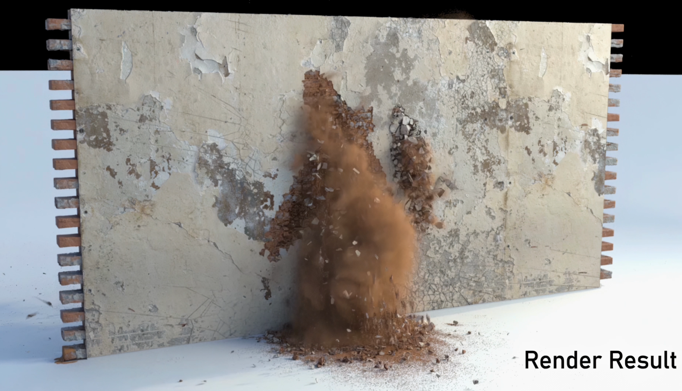
Wall Fracture Sim
This project is to test the pipeline combining procedural models and special effects, while taking into account the targeted optimization and modification of the custom sub-solver and the existing nodes of Houdini.
float ini_x = 0.12;
float ini_y = 0.0265;
float ini_z = 0;
int line = chi("line_num");
int up = chi("up_num");
float offset_x = ch("offset_x");
float offset_y = ch("offset_y");

for(int k =1; k < up+1; k++)
{
    int m = (k+1)%2;
    for(int i =1; i < line+1; i++)
    {
        vector p = set(ini_x*(i*2+m-1)+offset_x*(i-1),ini_y*2*(k-0.5)+offset_y*(k-1),ini_z);
        addpoint(0,p);
        string name = "wall" + "_" + itoa(i)+ "_" +itoa(k);
        int ptnum = (k-1)*line+(i-1);
        setpointattrib(0,"name",ptnum,name,"set");
    }
}
Technique Breakdown
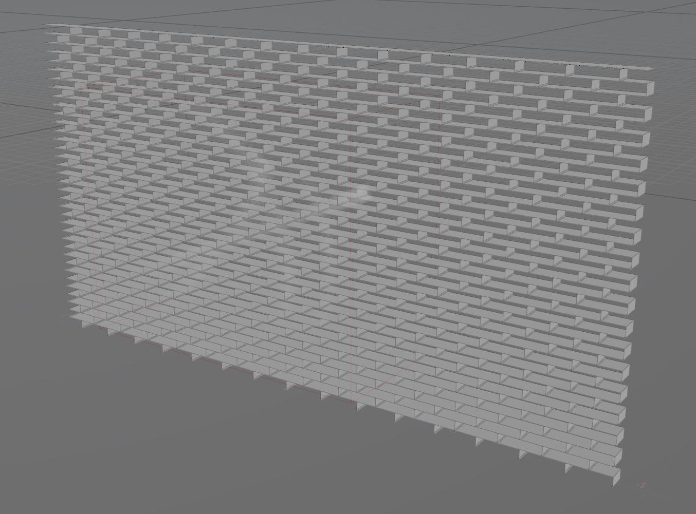
01 | Procedural Bricks Wall
The detail wrangle is used in the project to generate the anchor point of the brick. The basic principle is to perform displacement iteration according to the starting point, and at the same time offset the starting point of the brick by half the length in the even-numbered row.
Line Num ---Number of bricks per row
Up Num --- Number of bricks per column
Offset X --- The gaps between bricks in X axis direction
Offset Y --- The gaps between bricks

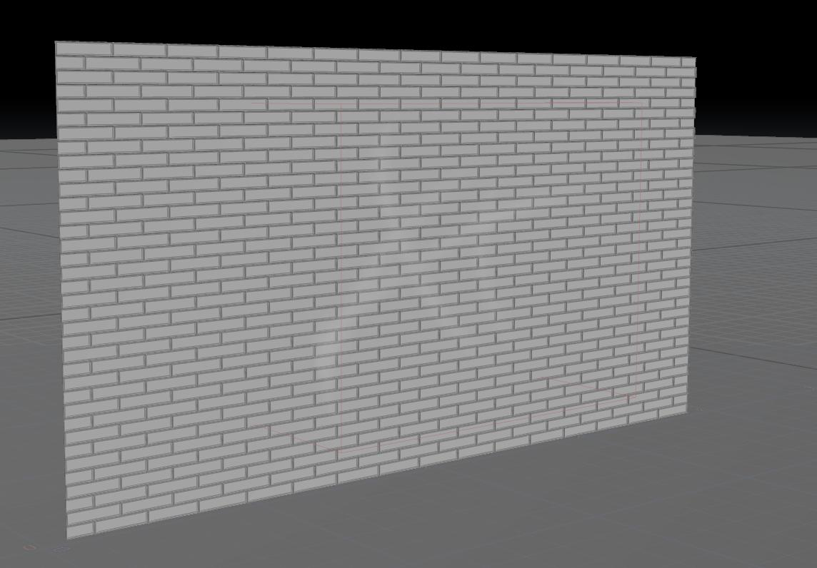
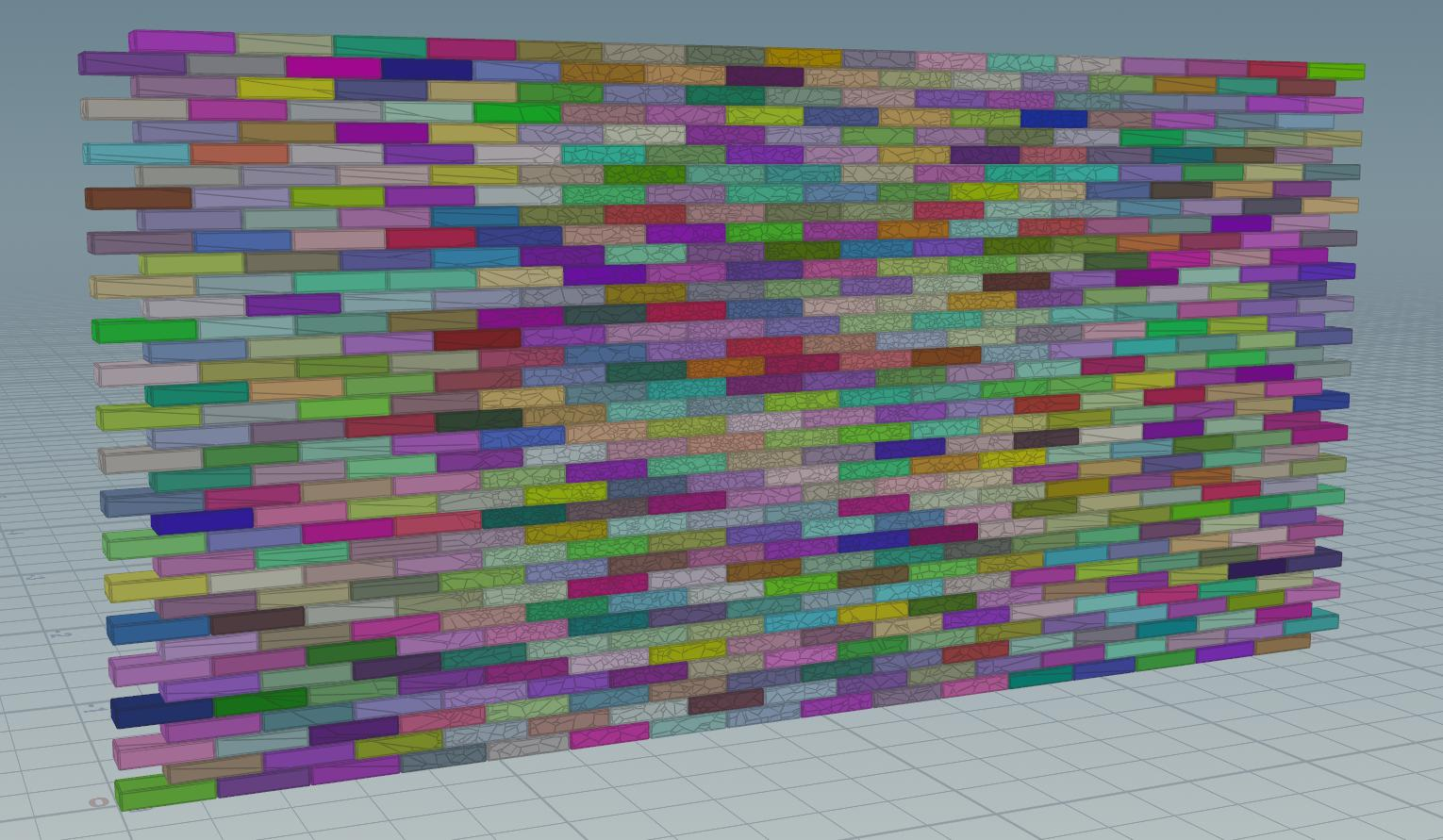
02 | Wall Construction
In the project, the wall structure is divided into 2 main parts, which are bricks, stucco surface on the bricks. The bricks are made by procedural modeling, and the paint and cement are obtained by subtracting the box and the bricks, so the entire wall can be adjusted procedurally without manual additional operations
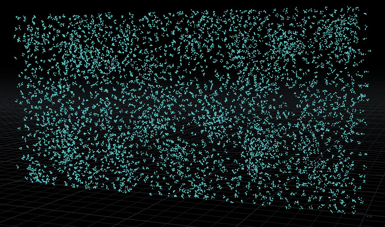
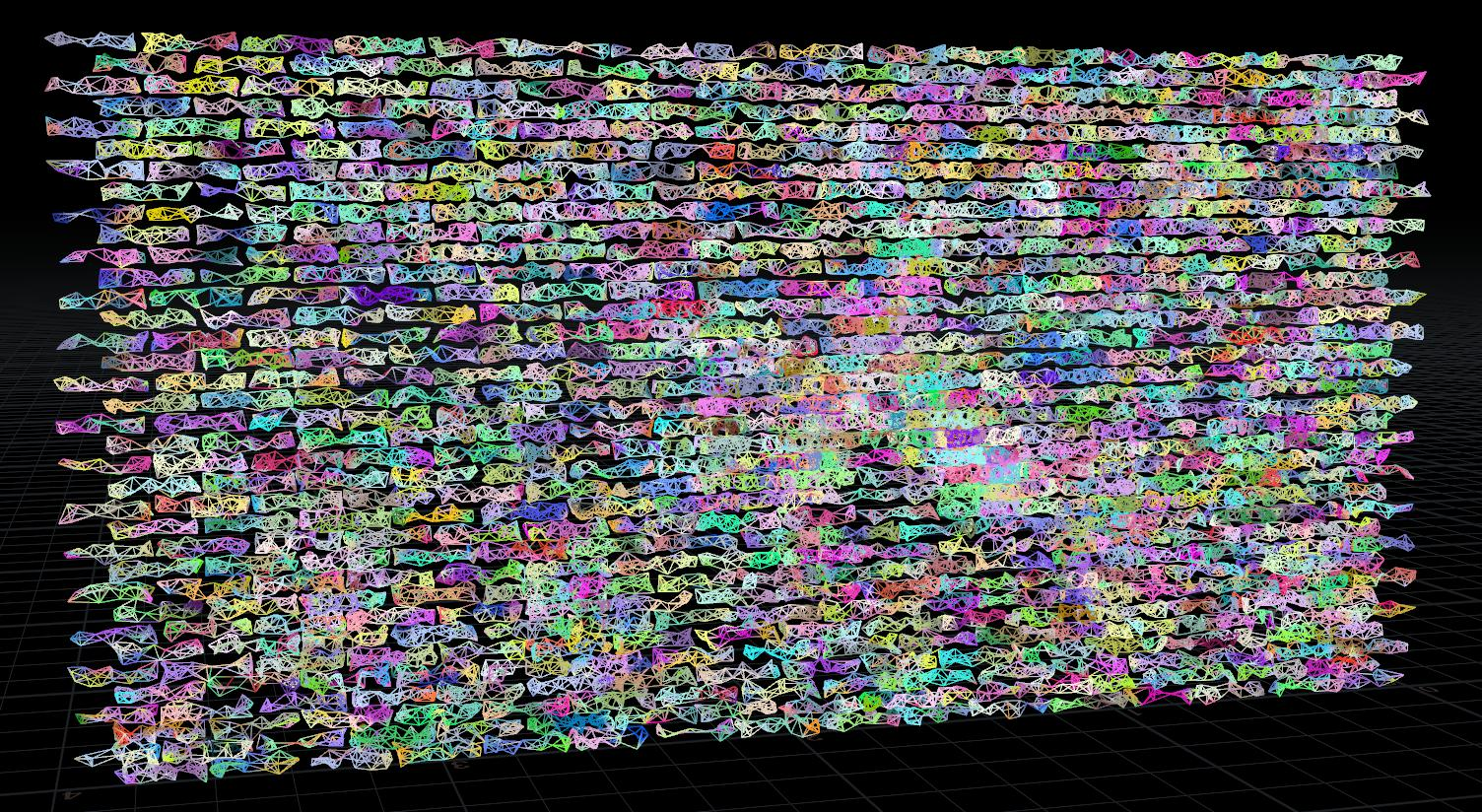
The bricks on the wall adopt Voronoi Fracture, add noise to density through volume vop, make the walking of the points more random.
*note: use the combination of copy and point jitter to gather more points in a small area in order to obtain some small fragments. The jitter scale should be set to a small number.

In order to get more fragments and details, the points used for voronoi Fracture will be in a considerable amount. In order to obtain the adaptive fragment size, it is necessary to optimize the points where the fragments are generated. The basic principle is to generate more points where the details need to be seen, and the area that will not be affected by the blade should be as small as possible in quantity.
Adaptive pieces optimize:
1. Use object merge to get the position and shape of the blade when it collides with the wall.
2. Convert the wall and the blade into a volume respectively, so that the scatter can spread the points inside the object.
3. Since the blade has a curvature, the point far away from the wall has little effect on the generation of the piece, so it is necessary to make the point as close to the wall as possible.
4. Use the attribute transfer node to assign the P attribute of the wall to the point of the blade
*note: Remember to check the Match P Attribute option in the attribute transfer node, otherwise the P attribute will not affect the real position of the object by default.


5. According to the bladede's range of influence, use the group by bounding region function in the group node to delete the points outside the area and keep the points in the core area

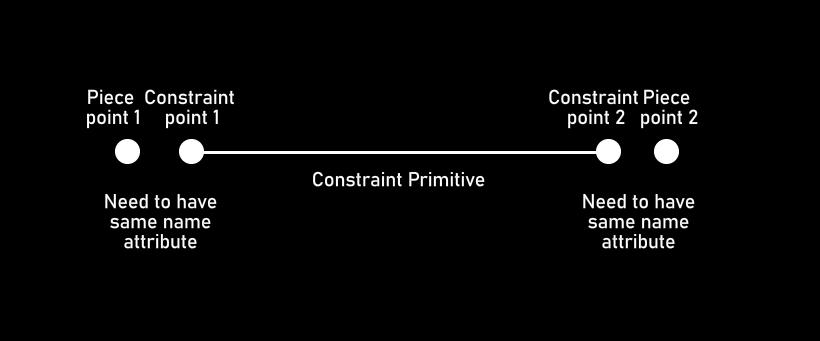
Constraint Principle
For constraints, the most important attribute is the name attribute at the point level. In Dop, constraints and fragments are poured in separately, so Dop needs an attribute to identify one end of the constraint and the corresponding constrained fragment, which is located at the point class The name attribute of the point class need to be used to identify the relationship between constraints and fragments.

In order to make the constraints of the bricks closer to the real life situation, here again the constraints are subdivided into the constraints within a single brick and the external constraints between the bricks.
*note: In order to better identify the individual bricks in the subsequent process, each brick is given a unique bricks attribute.
After the fragments of each brick have the bricks attribute used to distinguish the bricks, use "for each named primitive" to create constraints on the fragments of each brick. The internal properties of the bricks after creation should be as shown in the figure below, and there are no constraints between the bricks:
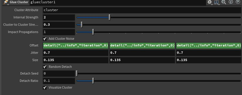
It should be noted that since the internal and external constraints of the bricks are edited separately, they need to be merged after editing. When merging, use the RBD Constraint Properties node to set the internal and external constraints to the same Glue Data Name, so that they can be identified in the Dop later. In addition, due to the previous cluster processing, the constraint strength between each cluster and within the cluster should be different, so the glue cluster is used to generate the Strengthvar attribute to multiply the set constraint strength.
*note:
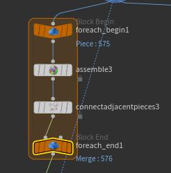
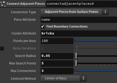
Similar to creating constraints within bricks, when creating constraints between bricks, you need to set Connect adjacent pieces to "Adjacent Pieces from Surface Points".And use the name attribute to distinguish independent fragments, and use the bricks attribute to distinguish fragments from different bricks


At the same time, in order to avoid the subsequent occurrence of uniform fragments in the simulation, these constraints need to be clustered. One thing to note is that the clusters inside the bricks must not exist in two different bricks at the same time. Therefore, for each named primitive is used here to offset the cluster noise of each brick to avoid cluster adhesion.

*note: The noise used to generate the cluster is based on the P attribute of the world coordinate system. Therefore, if the glue cluster is used to cluster the constraints within the bricks, a cluster will span two different bricks, which will distort the simulation effect.When a cluster is made for the internal constraints of each brick in the for loop, a large amount of offset is applied to the cluster noise of each brick based on the iterations of the for loop to avoid the same cluster between different bricks.

Since the role of blade is more similar to penetration and cutting, the traditional static object collision simulation is not suitable for this project Use object merge to import the blade model and scatter points in the converted volume.

03 | Create Customize Blade force
After this vop, the strength and direction of the force will be stored as the force attribute of the point class.
Inside Force Vop:
Distance - Get the distance between the point and the (0, 0, 0) point.
Fit range and ramp parameter - Generate force intensity based on distance。
Subtract - Get the force direction based on (0, 0, 0) point
Turbulence Noise - Randomize the direction and strength of the force
Force Direction Parameter - Add a specified vector after the generated force to freely control the direction of the force

04 | Applied Customize Blade force In Dop

Inside Dop network:
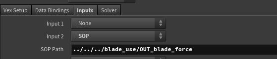
Geometry vop - Import the points with the force attribute created in sop into the dop network and apply the force into pack geometry.

Nearpoint - Find the nearest force point near each packgeo and output the point number of this point
Import Point attribute - Import the force attribute and P attribute of the point in the sop.
Distance and Fit range - Measure the distance between the nearest force point and pack geo, and convert this distance into a force-based intensity attenuation multiplier.
*note: The geometry vop cannot direct link with the sop node, therefore, you need to set the input of geometry vop in (geometryvop > inputs)
Pop wind - Add air resistance.
Pop speed limit - Prevent some very small fragments from flying out at an unreasonable speed
Sop solver - Define how the force attribute of the pack geo affects the constrained network

No. 0 interface of primitive wrangle is a constraint primitive, and No. 1 interface is a pack geometry connected to the dop network.
@forcept = nearpoint(1,@P);
@force = point(1,"force",@forcept);
@mag = length(@force);
if(@mag > ch("break_threshold")*@strength)
{
    //removeprim(0,@primnum,1);
    setprimgroup(0,"broken",@primnum,1,"set");

}
Primitive wrangle does something similar to geometry vop,First search for the nearest pack geo near the constraint point and get its point number. Obtain the force attribute by the point number, and use the if statement to determine whether the force attribute is greater than the threshold based on the strength of the constraint. If the force attribute is greater than the threshold, put the constraint primitive into the broken group。
*note:The broken group will be recognized by the constraint network, and the constraints belonging to the broken group will be automatically disabled
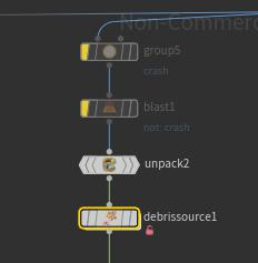
05 | Debris Source
*note:Before using Debris Source, be sure to unpack the input geometry. The operating principle of this node is to place the surface of the input geometry scatter points and determine whether the distance between the nearest two points changes more than a certain value. If it is more than a certain value, then Output this point for a period of time as a debris source
i@__otherid = point(1, "__otherid", @ptnum);
i@__released = point(1, "__released", @ptnum);
@age = point(1, "age", @ptnum);
if(i@__released)
    @age += @TimeInc;
else
{
    vector d = point(0, "P", i@__otherid);
    d -= v@P;
    float dist = ch("radius");
    if(length2(d) > dist * dist)
        i@__released = 1;
}

The debris source needs to scatter points in all the input geometry, so some useless input geometry can be deleted appropriately. It should be noted that the search radius, even if your fragment is very small, does not require a large search radius, but in this node, the distance threshold used to determine whether the point moves is the square of the search radius, so if the search radius is too small , It will cause the mobile judgment to be very sensitive, resulting in wrong results.