Vex drive mechanism
All mechanical structure movements in this project are linked by vex script, and the robot running speed, stop market, rotation speed, and maximum rotation angle are controlled programmatically by a custom solver.
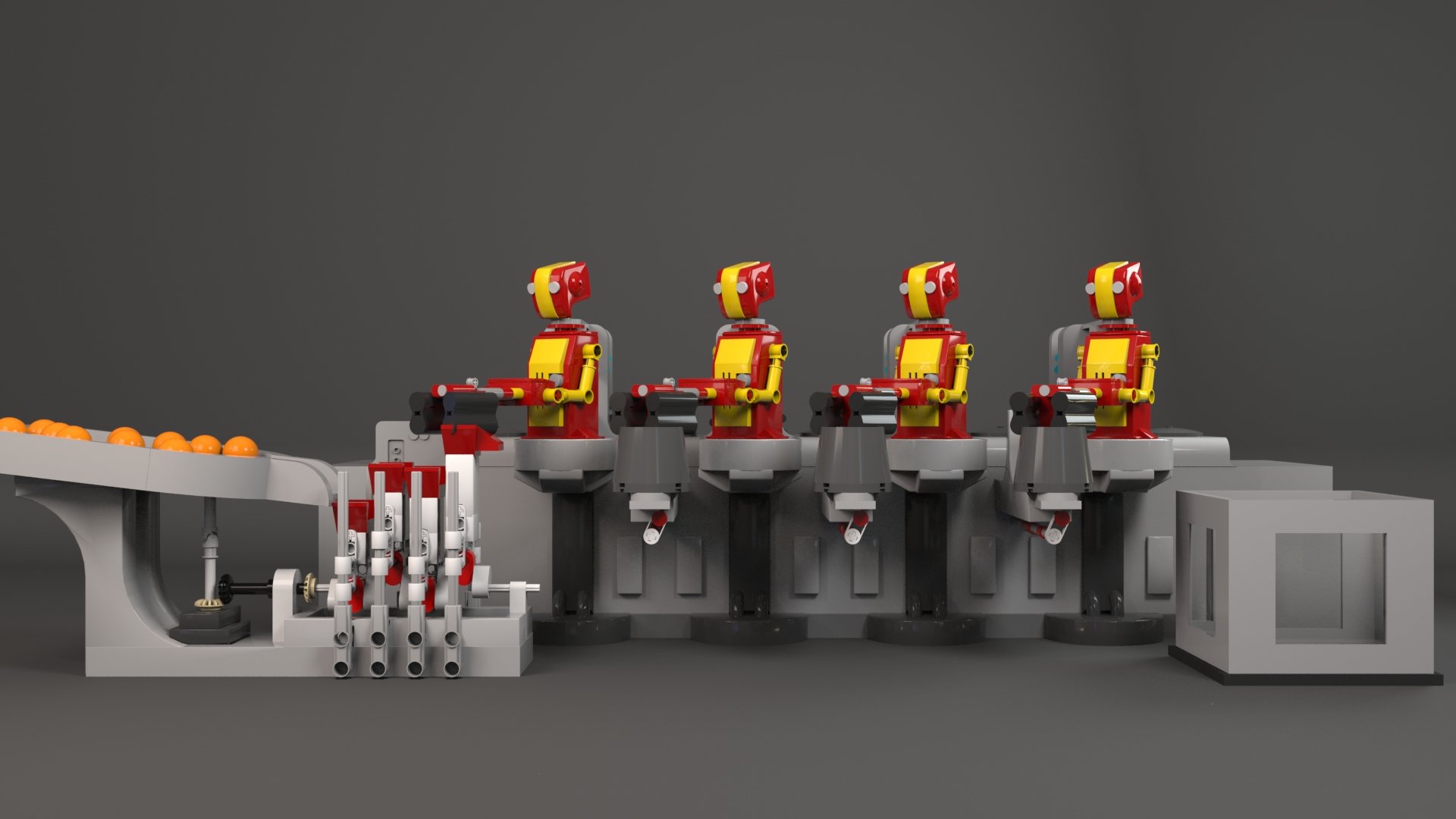
Reference and Final Render


Technical Break Down
float amp = ch("max_angle");
@Frame_code = 1+@Frame_code;

if(@trans_y > ch("tolerence")*amp || @trans_y < -ch("tolerence")*amp){
    if(@stop <0){
        @count = @count - 1;
       }
    }

if(@count > -ch("stop_time") && @count <0){
    @Frame_code = @Frame_code -1;
    }

if(@count == -ch("stop_time")){
    @count = 0;
    @stop = 1;
    }

@stop = @stop-1;
@trans_y = amp*sin((@Frame_code+ch("offset"))/ch("Period"));
In most procedural animation, @Frame will be the parameter which motivate the animation. In this project, the robot’s animation is Periodic movement with intermittent pauses. In order to deal with the pauses, I create a solver,it will use the @Frame to generate a New Frame code attribute.
01 | The Custom Frame Code Solver

Basically, what the solver did is to make the Frame code add 1 by each frame, However, when the movement reach the tolerance setting, the solver will stop adding the frame code and start a new count down called count, Only if the count down number reach the stop time setting, the Frame code will restart to caculate.
Also, to avoid the movement stuck when the count down is over, another count down called”stop” will be activate, in the setting time ,the solver will ignore the Tolerance setting.

02 | The Capsule Structure and Animation Match
In this Project, there are many Capsule Structure, and are link to each other, in order to apply the animation easier , I use the line to create the model.


In order to ensure the procedural model will have the right direction, use the point wrangle to set the normal and up attribute for each point.
Then use the point number to split the point at the endpoint and the point at the middle, copy to circle to the endpoint and a grid to the middle point.


Finally, simple poly extrude will finish the model. The point control are also convenient to link each other, Just apply another point’s P attribute to the relative point will get the result.
The Clip of the Robot need to deal with a lot simulation, In this project, I set the clip to the Statistic object, so it can move along the animation I set in SOP.
03 | The RBD Collision Proxy

To achieve this, I use the sdf field as the collision volume proxy, so that I can set the invisible plate to ensure the step2.


The movement of the sphere in the clip is a little bit complex, The clip needs to be able to block the ball when it is accelerating, to be able to pick up and drop the ball in a suitable position, and to ensure that it will not fall from below during the process of clamping.